3D
Smooth Surfaces in 3D Printing | Seams Ironing
Surface quality is the first impression of a 3D part. In Bambu Studio you can gain “professional face” with two

OrcaSlicer’s tolerance test solves a common problem in 3D printing: parts that do not fit correctly when assembled.
This simple test identifies the exact tolerance your printer needs to create parts that fit the first time. In just 10 minutes you can get a reference value that will improve the accuracy of all your designs.
This guide explains the complete process: how to run the test, interpret the results and apply what you learn. No fuss, no detours, just practical information to get better results in your 3D printing.
The OrcaSlicer tolerance test is a calibration tool that allows you to determine the dimensional accuracy of your 3D printer. It consists of a simple model with six hexagonal holes, each with a different tolerance, and a hexagonal piece to test the fit in each hole.
Tolerance in 3D printing refers to the difference between the theoretical dimensions of a model and the actual dimensions of the printed part. This difference arises from multiple factors: the characteristics of the printer, the material used and the printing parameters.
Performing this test provides you with three specific benefits:
Best of all, this test requires only 10 minutes of printing and consumes only 3.10 grams of filament. It’s a minimal investment for a significant improvement in the quality of your projects.
Accessing the tolerance test in OrcaSlicer is very simple:


The model will be loaded automatically. From here, you can use your usual settings to slice the model, or make some specific adjustments.
Once the test model is loaded into OrcaSlicer, it is time to prepare it for printing. The model consists of two parts: a rectangular base with six hexagonal holes and a hexagonal test piece.
To obtain accurate results, you should avoid using certain functions that affect dimensions:
These functions could alter the precise dimensions of the test, which would invalidate the results. The objective is to evaluate the natural dimensional accuracy of your printer without software corrections.
Here are the steps to prepare and print the model:
Once the printout is completed, follow these steps to draw conclusions:


This value will indicate the natural tolerance of your 3D printing system to the filament used.
Once you have identified the hole with the best fit, you know the optimum tolerance for your specific printer and filament. This numerical value (0.0mm, 0.05mm, 0.1mm, 0.2mm, 0.3mm or 0.4mm) has immediate practical applications.
To apply the result in your slicer and projects:
This setting will cause OrcaSlicer to automatically compensate the dimensions of your models to achieve the precise fit you determined with the tolerance test.

For parts with specific holes, there is also the “XY Hole Compensation”, which you can set to the same value obtained to ensure that the holes have the correct dimensions.
A practical example: if you determined that your optimum tolerance is 0.1mm, when designing a male-female assembly system:
This information is especially valuable for printing functional mechanisms, snap-fit parts, and components that require relative movement to each other.
The tolerance varies significantly depending on the material used. This is mainly due to the different shrinkage experienced by each type of filament as it cools.
| Material | Tolerance characteristics | Recommendation |
| PLA | Minimal shrinkage (0.2-0.5%) | Generally requires smaller tolerances (0.1-0.2mm). |
| PETG | Moderate contraction (0.4-0.7%) | Medium tolerances (0.2-0.3mm) may be required. |
| ABS | High shrinkage (0.8-1.5%) | Usually requires larger tolerances (0.3-0.4mm). |
| TPU/Flexible | Compressible, less predictable | Needs specific tests for hardness |
| Nylon | Moisture absorbing, variable dimensions | Perform the test with dry material |
Important recommendation: Perform the tolerance test for each type of filament you usually use. Even between brands of the same material (e.g. different PLA) there can be significant variations.
It is not necessary to do this with every new coil of the same type and brand. However, you should repeat the test when:
If the best fit seems to be between two values (e.g., between 0.2mm and 0.3mm), you can:
Yes, this test is compatible with any FDM (Fused Deposition Modeling) printer. The specific function “Orca Tolerance Test” is only available in OrcaSlicer, but you can find similar models in repositories like Thingiverse or Printables if you use other software.
Temperature can significantly influence the results:
For optimum results, test at the temperatures you normally use for each material.
Smooth Surfaces in 3D Printing | Seams Ironing
Surface quality is the first impression of a 3D part. In Bambu Studio you can gain “professional face” with two
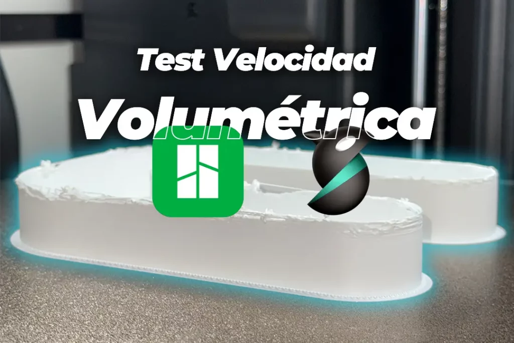
Volumetric Speed Test | Increase 3D Printing Speed
Want to print faster without losing quality? The key is to know the volumetric speed limit of your 3D printer

OrcaSlicer Tolerance Test: Complete 3D Printing Guide
OrcaSlicer’s tolerance test solves a common problem in 3D printing: parts that do not fit correctly when assembled. This simple
3D Printing Shrinkage Test: Quick Guide 2025
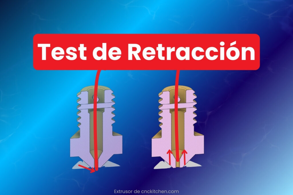
Reducing stringing in 3D printing is not a matter of luck, but of good setup. Learn how to do a

Flow Test in 3D Printing: Quick Solution
Filament flow calibration is one of the most important settings in 3D printing. This calibration is done by one or
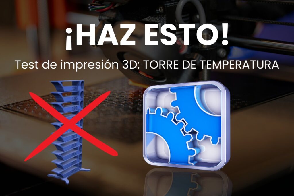
PLA Temperature Tower for 3D Printing: Guide 2025
Why not just follow the manufacturer’s guide, if only! Filament specifications are a good starting point, if you 3D print
We promise to send you only what interests you: practical advice, special discounts and access to free samples of our filaments. No spam, only benefits.